


CNC toolpath software turns your design file into machine instructions through one chain: your CAD design is translated by CAM software into toolpaths, a post-processor rewrites those paths in your machine’s dialect, and the resulting G-Code drives the cut. Every CNC disaster you have ever heard about — the bit through the spoilboard, the part cut at half size — is a break in that chain, not a mystery. This guide walks the chain link by link, teaches you the three toolpath types that cover most furniture work, and gives you the checks that keep the tears out of the process.
Key takeaways
- The chain is design → CAM → post-processor → machine; verify each link separately and errors stop hiding.
- Three toolpath types do most furniture work: profile (cutting outlines), pocket (clearing areas) and drill (holes for hardware and dowels).
- Feeds and speeds are a balance, not a maximisation: the right pair makes clean chips, the wrong pair makes dust, burning or broken bits.
- Simulation is your cheapest material — run it, check extents and depths, and never let the first run of a file be in real stock.
- Most file errors are mundane: wrong units, wrong origin, wrong post-processor, or a design exported at the wrong scale.
What does cnc toolpath software actually do?
It converts geometry into movement. Your design file knows shapes — rectangles, circles, outlines — but a CNC machine knows only positions and speeds: move to this point, lower the bit, travel along this line at this feed rate. Toolpath software (the CAM stage) reads your shapes and plans the cutter’s journey: which tool, which order, how deep per pass, where to start and where to lift clear.
The output of that planning is G-Code, the near-universal language of machine control — a text file of commands your controller executes line by line. Because it is plain text with a documented structure, you can read it, check it and even fix it by hand; the G-Code reference on Wikipedia is worth bookmarking for the day a file does something strange and you need to see why.

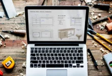


The chain, link by link: design → CAM → post-processor → machine
Each link in the chain has exactly one job, and your first diagnostic skill is knowing which link failed when a cut goes wrong. Treat the four stages as separate deliverables, each with its own check.
Link 1: The design file
Your CAD output should be clean geometry at true scale, in known units, with the part positioned deliberately. Export closed outlines for anything you intend to profile or pocket — open paths and stray duplicate lines are the seeds of half of all CAM confusion. If your design tool generates the part parametrically, confirm the exported dimensions against one known measurement before the file goes anywhere near CAM.
Link 2: CAM — where toolpaths are born
In CAM you choose the tool, assign operations to geometry, and set depths, passes and speeds. This is where craftsmanship now lives: the machine cuts what it is told, so the decisions that decide quality — operation order, stepover, tabs, lead-ins — are all made here, by you, at a desk.
Link 3: The post-processor
The post-processor translates generic toolpaths into the exact dialect your controller expects: its start codes, its arc handling, its units, its tool-change behaviour. The wrong post produces files that alarm out, move oddly or — worst — run with silent differences. Set your machine’s post once, save it as your default, and treat any change to it as a reason to re-prove the next file.
Link 4: The machine and controller
The controller reads the file and moves iron. Your jobs here are setup jobs: fix the stock, set the work origin to match the CAM origin, confirm the tool in the spindle is the tool the file expects, and set the Z zero honestly. Most “software errors” reported by beginners are setup mismatches at this link.
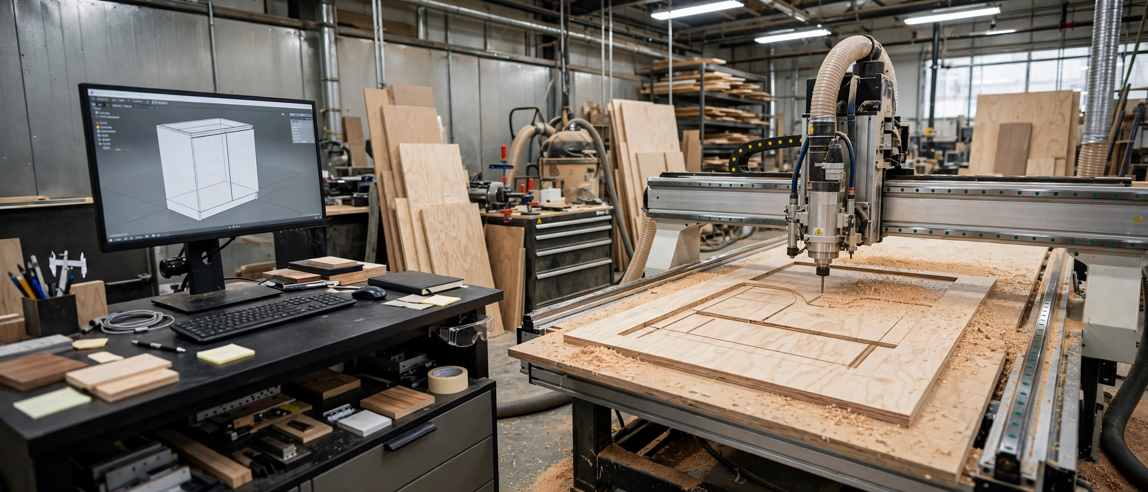
The three toolpath types you will use daily
Profile, pocket and drill operations cover the overwhelming majority of furniture CNC work. Learn what each one is for and you can read any CAM screen with confidence.
| Toolpath | What it does | Typical furniture use | Watch out for |
|---|---|---|---|
| Profile | Follows an outline, cutting on, inside or outside the line | Cutting panels and parts to final shape | Cut side (inside vs outside) flips your dimensions |
| Clears material inside a boundary to a set depth | Recesses, dados, hinge cups, sign lettering | Stepover too wide leaves ridges and islands | |
| Drill | Plunges at points, with pecking cycles for depth | Shelf-pin holes, dowel holes, hardware boring | Wrong diameter or depth pattern ruins a whole panel |
| V-carve / engrave | Varies depth with width using a pointed bit | Labels, logos, decorative lines | Depth surprises on narrow details |
| Surface / 3D finish | Sweeps a ball-nose bit across a 3D shape | Curved seats, sculpted parts | Very long run times if stepover is timid |
Profile cutting, explained
A profile cut follows your outline with the bit offset by its radius, so the finished part matches the drawing. Choose whether the tool runs outside the line (for the part itself) or inside (for a hole or window), set the depth in passes the bit can handle, and add tabs — small uncut bridges — so the finished part does not shift in the final seconds of the cut.
Pocketing, explained
A pocket clears an area down to a floor depth. The software steps the bit across the area with a set overlap (stepover); too little overlap wastes time, too much leaves uncut ridges. For deep pockets, CAM steps down in stages — respect those stages, because a bit buried to full depth in one plunge is a bit asking to break.
Feeds and speeds, at the level that keeps you safe
Feed rate is how fast the bit travels through the material; spindle speed is how fast it spins. Together they decide the chip load — how much material each cutting edge bites. You do not need formulas memorised to work safely; you need the symptoms. Chips and curls mean the balance is right. Fine dust means the bit is rubbing rather than cutting — usually spinning too fast or feeding too slow. Burn marks mean heat is building for the same reason. Chatter and screaming mean the opposite extreme or a loose setup. Change one variable at a time, in small steps, and write down what worked for each material and bit: your own notebook becomes the only feed chart that matches your machine.
Before you press start: the simulation checklist
- Run the full simulation in your CAM software and watch the tool, not the part — you are checking behaviour, not beauty.
- Verify the job extents: the bounding box of the cut must match your stock, with margin.
- Check maximum depth against stock thickness — decide deliberately whether you cut through, and into what.
- Confirm the origin in the file matches the origin you will set on the machine: same corner, same face.
- Confirm units: a file interpreted in inches that was written in millimetres is 25.4 times wrong.
- Check the first lines of the G-Code: correct post, sane start codes, the right tool number.
- Do a dry run above the stock — an “air cut” — for any file that is new, edited or regenerated.

How do you get from a furniture design to a cut file without rework?
You keep the design parametric and let one environment carry it from dimensions to toolpaths. The rework in most shops is not cutting — it is translation: redrawing in a second program, re-measuring, re-exporting, and introducing a fresh error at every hand-off. When your design tool produces the cut list and machine files from the same model — the approach taken by Sketch3D-Art Studio Pro, which exports CNC-ready files from the furniture design itself — the chain shortens and the error surface shrinks with it. Whichever tools you use, study the failure patterns in our guide to prototyping tools and flawless first results: the prototyping discipline there is exactly the discipline that makes first cuts boring — in the good way.
Common mistakes
Posting with the wrong post-processor. The file looks fine and the machine disagrees. Lock your machine’s post as the CAM default and never post “just to try” another one on real stock.
Trusting the export scale. A design exported at 96% or in the wrong units produces a beautiful, wrong part. Measure one known feature in CAM before generating any toolpath.
Setting the origin by habit. CAM assumed top-left; you zeroed at centre. The result is a part cut half off the sheet. Say the origin out loud at both ends of the chain.
Cutting to full depth in one pass. Deep single passes overload bits, tear edges and break tools. Let CAM step down in sensible increments — the extra minutes are cheaper than the bit and the panel.
Skipping the air cut on “identical” files. Regenerated files are new files. Any change — a resized panel, a re-post, a different tool — earns a dry run above the stock.
Frequently asked questions
Do I need separate CAD and CAM programs?
Not necessarily. Many design tools include CAM, and some furniture platforms generate machine files directly from the design. What matters is not the number of programs but the integrity of the chain — clean design, deliberate toolpaths, the right post-processor.
What is a post-processor, in one sentence?
It is the translator that rewrites generic toolpaths into the exact G-Code dialect your specific machine controller expects. Same toolpaths, different post, different file — which is why posting for the wrong machine is such a common and dangerous error.
Why did my part come out the wrong size?
Almost always one of three causes: a units mismatch (millimetres read as inches or the reverse), an export at the wrong scale, or a profile cut run on the wrong side of the line. Check those three, in that order, before suspecting the machine.
How deep should each pass be?
As a conservative habit, step down in increments related to the bit’s diameter rather than the full depth at once, and let material hardness guide you — harder stock, shallower passes. Your CAM defaults are a starting point; your test cuts in offcuts are the authority.
Can I edit G-Code by hand?
Yes — it is plain text, and small edits such as changing a feed rate or removing a stray move are routine for experienced operators. Edit a copy, note what you changed, and simulate or air-cut afterwards; the file you fixed by hand is a new file.
Keep learning: toolpaths start upstream, in the design itself — our CNC-ready furniture design guide shows how to design pieces your router can actually cut.
Conclusion
You now own the whole chain: clean design in, deliberate toolpaths in CAM, the correct post-processor for your machine, and a setup that matches the file’s assumptions — verified by simulation and an air cut before real stock is involved. Master the three daily toolpaths, learn your machine’s feed-and-speed symptoms, and G-Code stops being a cliff edge and becomes a checklist. Your next step: take a file you have already cut successfully, re-post it, and run the seven-point checklist on it to calibrate your eye. Which link in your chain has caused you the most grief so far?




 English
 العربية
 Français